How To Connect PLC To Servo Drive?
Key Takeaway
To connect a PLC to a servo drive, follow these steps. First, ensure both devices are powered off to prevent any electrical hazards. Gather the necessary cables and connectors. Typically, you’ll use a communication cable that matches the protocol supported by both the PLC and servo drive, such as Ethernet, RS-232, or RS-485.
Next, connect the communication cable from the PLC’s communication port to the servo drive’s corresponding port. After establishing the physical connection, power on both devices. Configure the PLC software to recognize the servo drive. This usually involves setting the correct communication parameters such as baud rate, data bits, and parity.
Finally, write a control program in the PLC to send commands to the servo drive. Test the connection by sending simple commands to ensure proper communication and control. If issues arise, check the cable connections and communication settings. This process ensures a reliable and efficient integration of your PLC and servo drive systems.
Introduction to PLCs and Servo Drives
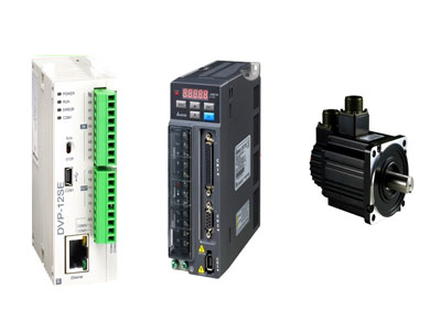
Programmable Logic Controllers (PLCs) and servo drives are essential elements in modern industrial automation systems. PLCs are specialized digital computers designed to manage and automate industrial processes, such as controlling machinery on factory assembly lines, regulating production equipment, and ensuring seamless operation of complex systems. They receive inputs from various sensors and switches, process the data according to pre-programmed instructions, and send control signals to actuators like motors.
Servo drives, on the other hand, are critical for controlling servo motors. They interpret command signals from PLCs to regulate the motor’s speed, position, and torque with high precision. This precise control is vital for applications requiring accurate motion and positioning, such as robotics, CNC machinery, and automated manufacturing lines. By integrating PLCs with servo drives, industries can achieve enhanced efficiency, improved accuracy, and increased productivity, ultimately leading to more reliable and sophisticated automation solutions.
Communication Protocols Used
Several communication protocols can be used to connect PLCs to servo drives, each with its specific advantages and use cases:
Ethernet/IP: Commonly used for its high-speed data transfer and widespread compatibility with industrial equipment. It allows for robust and flexible network configurations.
Modbus: A widely used protocol that provides simplicity and reliability. It’s suitable for applications that don’t require high-speed communication.
CANopen: Often used in motion control applications, it offers real-time data exchange and high reliability, making it ideal for connecting PLCs to servo drives.
PROFINET: A real-time Ethernet standard for automation, providing high-speed communication and seamless integration with various industrial devices.
RS-485: An older protocol, but still used for its simplicity and effectiveness in short-distance communication with lower data rates.
Choosing the right protocol depends on the specific requirements of your application, including the speed of communication, the complexity of the system, and the compatibility with existing equipment.
Step-by-Step Connection Guide
Connecting a PLC to a servo drive involves several key steps:
Preparation: Gather all necessary components, including the PLC, servo drive, appropriate cables, and any required software. Ensure both the PLC and servo drive are powered off before making any connections.
Wiring:
Power Connections: Connect the power supply to both the PLC and the servo drive, ensuring they are grounded properly to avoid electrical noise.
Communication Cable: Connect the communication cable between the PLC and the servo drive. The type of cable depends on the chosen communication protocol (e.g., Ethernet cable for Ethernet/IP, twisted-pair cable for RS-485).
Configuration:
PLC Configuration: Use the PLC’s programming software to configure the communication settings. This includes setting the IP address (for Ethernet-based protocols) or baud rate and parity (for serial communication protocols).
Servo Drive Configuration: Access the servo drive’s configuration interface (usually via a PC and dedicated software) to set matching communication parameters, such as the IP address, baud rate, and data format.
Testing:
Initial Power-Up: Power on the PLC and the servo drive, ensuring that all connections are secure and that there are no fault indicators.
Basic Communication Test: Send a simple command from the PLC to the servo drive (e.g., move to a specific position or adjust speed) to verify communication.
Monitoring: Use the monitoring tools provided by the PLC and servo drive software to ensure that commands are being received and executed correctly.
Common Issues and Troubleshooting
Several common issues may arise when connecting PLCs to servo drives:
No Communication: If there is no communication between the PLC and servo drive, check all cable connections, ensure that both devices are powered on, and verify that communication settings match on both ends.
Data Errors: Data transmission errors can occur due to electrical noise or improper configuration. Use shielded cables, ensure proper grounding, and double-check configuration settings.
Lag or Delay: Communication lag can be caused by network congestion or inappropriate settings. Optimize network traffic and ensure the baud rate is appropriate for your application.
Inconsistent Performance: If the servo drive does not respond consistently, inspect the feedback devices (encoders or resolvers) and ensure they are correctly installed and calibrated.
Best Practices for Reliable Connection
To ensure a reliable connection between PLCs and servo drives, follow these best practices:
Proper Grounding and Shielding: Electrical noise can interfere with communication. Use shielded cables and ensure proper grounding to minimize noise.
Regular Maintenance: Perform routine maintenance on all components, checking connections, and ensuring that all software is up-to-date.
Documentation: Keep detailed records of all configurations and connections. This makes troubleshooting easier and ensures that any future modifications are straightforward.
Training: Ensure that all personnel involved in operating and maintaining the system are well-trained. Understanding the system’s intricacies can prevent many common issues.
Conclusion
Effectively connecting PLCs to servo drives is essential for achieving optimal performance in industrial automation systems. Understanding the various communication protocols, such as Ethernet/IP, Modbus, and Profibus, is critical for establishing a robust connection. Following a detailed step-by-step connection guide ensures that all components are properly interfaced and configured. Addressing common issues, such as signal interference or configuration errors, helps maintain system reliability. Adhering to best practices, including proper grounding, shielding, and regular maintenance, further enhances the stability and efficiency of the integration. This meticulous approach results in improved precision, increased productivity, and higher quality outcomes in automated industrial processes, ultimately contributing to the overall success and competitiveness of manufacturing operations.