How Are Actuators Configured To Respond To Limit Switch Signals?
Key Takeaway
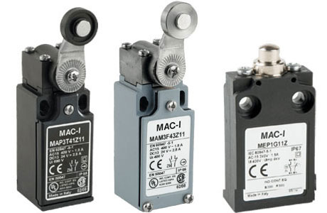
Actuators are configured to respond to limit switch signals by physically interacting with the switch to trigger an electrical response. When a moving part or object makes contact with the actuator, it transfers the motion to the internal mechanism of the limit switch. This action either opens or closes the electrical contacts, sending a signal to the connected system.
The configuration depends on the type of motion involved. For rotary motion, the actuator may use cams or rollers, while linear motion uses plungers or levers. These signals are then used to control machinery, stop operations, or signal a system to take further action. This precise interaction ensures that actuators and limit switches work seamlessly in automation systems, enhancing control and safety in industrial environments.
Importance of Actuator Configuration in Automation
Actuator configuration is a cornerstone of modern industrial automation. Actuators, responsible for executing physical movements such as opening valves or moving mechanical arms, rely on precise signals to perform their tasks. This precision becomes critical in complex systems where even slight misalignments can disrupt operations.
Limit switches play a vital role in ensuring accuracy. These mechanical devices act as checkpoints, signaling actuators to start, stop, or change direction based on their position. Configuring actuators to respond effectively to limit switch signals ensures seamless coordination, enhancing system reliability and safety.
Without proper configuration, actuators may overrun their intended range or fail to halt operations in emergencies, leading to inefficiencies and potential damage.

How Limit Switches Communicate with Actuators
Limit switches and actuators communicate through electrical or mechanical signals. When an actuator moves a component, such as a conveyor belt or robotic arm, it eventually triggers the limit switch. The switch then sends a signal—often an electrical pulse—to the control system, which interprets the input and adjusts the actuator’s operation accordingly.
For example, in a conveyor system, a limit switch might detect when a package reaches the end of the line. The switch sends a signal to the control unit, instructing the actuator to stop the conveyor. This real-time feedback ensures that the actuator halts precisely at the right moment, preventing over-travel or collisions.
The configuration ensures synchronization. Limit switches act as sensors that provide actionable data, while actuators execute physical tasks based on that data. Together, they create a feedback loop that is critical for accuracy and reliability in automation systems.
Steps to Configure Actuators for Limit Switch Signals
Properly configuring actuators to respond to limit switch signals involves several systematic steps:
Identify Application Requirements: Start by understanding the specific requirements of the application. Determine the range of motion for the actuator and the points at which limit switches need to be triggered.
Position the Limit Switches: Place the limit switches in precise locations where they can detect the actuator’s position accurately. For example, if the actuator moves a robotic arm, position switches at both the starting and ending points of the arm’s range.
Connect to the Control System: Integrate the limit switches with the actuator’s control system, such as a programmable logic controller (PLC). Ensure proper wiring and confirm that signals from the limit switches are received and interpreted correctly.
Calibrate the System: Test the setup to ensure the actuator responds appropriately to the limit switch signals. Adjust the switches or actuator parameters as needed to achieve smooth operation.
Perform Routine Testing: Regularly test the configuration to ensure it remains functional over time. Environmental factors or wear and tear can affect performance, making periodic checks essential.
Following these steps ensures the system operates with precision and reliability, minimizing errors and maximizing efficiency.
Applications Benefiting from Configured Actuators
Configured actuators responding to limit switch signals are indispensable in various industrial applications. One common use is in conveyor systems. Here, limit switches detect the position of packages, signaling actuators to stop or redirect the conveyor belt as needed. This ensures accurate sorting and packaging.
In robotic systems, actuators drive the movement of arms or grippers, while limit switches define safe operating ranges. This prevents overextension, ensuring the robot operates within its intended workspace.
Valve control systems in industries like oil and gas also rely heavily on this configuration. Limit switches signal actuators to fully open or close valves, maintaining precise flow control and preventing leaks.
Another application is in material handling, where actuators move heavy loads. Limit switches define endpoints, ensuring safety and precision during operations such as lifting, lowering, or rotating. These examples demonstrate how configured actuators and limit switches create reliable and efficient systems.
Troubleshooting Configuration Issues in Actuator Systems
Even the best-configured systems may encounter issues over time. Troubleshooting these problems begins with diagnosing the communication between the limit switches and actuators. A common issue is misalignment, where the actuator fails to trigger the limit switch at the right moment. Repositioning the switch or recalibrating the actuator can resolve this.
Electrical faults, such as loose connections or signal interference, can also disrupt operations. Inspecting the wiring and ensuring proper signal continuity often addresses these issues.
Environmental factors, like dust, moisture, or temperature fluctuations, may affect the performance of both limit switches and actuators. Using components with appropriate protection ratings and conducting regular maintenance mitigates these challenges.
Finally, software integration problems can arise, particularly in systems controlled by PLCs. If the actuator does not respond to limit switch signals, verifying the control program and updating firmware might be necessary. Proactive troubleshooting keeps the system running efficiently and avoids costly downtime.
Conclusion
Configuring actuators to respond to limit switch signals is a fundamental aspect of industrial automation. Limit switches provide precise feedback, ensuring actuators perform their tasks with accuracy and reliability. Proper configuration enhances safety, reduces errors, and extends the lifespan of equipment.
For engineers entering the field, understanding this process is crucial. By following systematic steps and addressing potential challenges proactively, industries can achieve seamless operations and robust automation systems. The synergy between actuators and limit switches is a cornerstone of modern manufacturing excellence.
