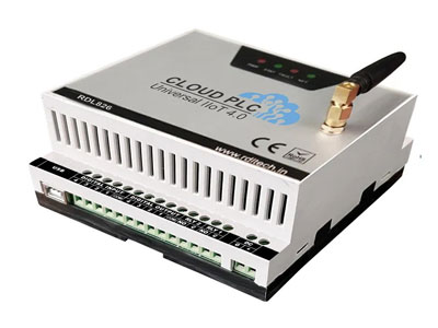
How To Connect 4-20ma Sensor To PLC?
Key Takeaway
To connect a 4-20mA sensor to a PLC, first, identify the sensor’s output terminals and the PLC’s analog input terminals. Connect the positive terminal of the sensor to the positive analog input on the PLC. Next, connect the negative terminal of the sensor to the common ground on the PLC. Ensure proper wiring to avoid any signal interference. Configure the PLC to read the 4-20mA input signal by setting up the correct input channel in the PLC software. Finally, calibrate the system to ensure accurate readings. This setup enables the PLC to accurately measure and process the sensor’s data.
Understanding 4-20mA Sensors
4-20mA sensors are widely used in industrial automation for measuring various process variables such as temperature, pressure, and flow. The 4-20mA current loop is a robust and noise-resistant method for transmitting analog signals over long distances. The current loop starts at 4mA, representing the lowest measurement value, and scales up to 20mA, indicating the highest measurement value. This range allows for the detection of open or short circuits, making it a reliable option for critical measurements.
Wiring the Sensor to the PLC
Wiring a 4-20mA sensor to a PLC is a straightforward process that ensures accurate data acquisition. Follow these detailed steps to ensure proper wiring:
Identify Terminals: Begin by locating the 4-20mA output terminals on the sensor. Typically, these terminals are labeled, but refer to the sensor’s manual if necessary. Similarly, identify the corresponding analog input terminals on the PLC, usually found in the PLC’s documentation.
Connect the Sensor: Attach the positive terminal of the sensor output to the positive terminal of the PLC’s analog input. Use high-quality, shielded cables to minimize electrical noise interference. Secure the connections firmly to ensure a stable and reliable signal.
Power Supply: Verify if the sensor requires an external power supply. Some sensors are loop-powered, meaning they draw power from the current loop itself. If an external power supply is needed, connect it according to the sensor’s specifications. Ensure the voltage and current ratings match the sensor’s requirements to avoid damage.
Check Polarity: Double-check the polarity of all connections. Incorrect polarity can damage both the sensor and the PLC. The positive terminal of the sensor should connect to the positive input on the PLC, and the negative terminal should connect to the common ground.
Properly wiring a 4-20mA sensor to a PLC is crucial for obtaining accurate and reliable measurements. Ensure all connections are secure, use appropriate cables, and verify the power supply requirements to maintain the integrity of your data acquisition system. Regular inspections and maintenance can prevent wiring issues and ensure continuous, accurate data flow.
You May Like to Read
Configuring the PLC for 4-20mA Input
Configuring the PLC to read a 4-20mA input involves setting up the analog input channel and scaling the input signal to the desired engineering units. Here’s how to do it:
Analog Input Configuration: Open the PLC’s configuration software and navigate to the analog input settings. This is typically done through a dedicated configuration interface or programming environment provided by the PLC manufacturer.
Select Input Type: Set the input type to 4-20mA for the corresponding analog input channel. This ensures that the PLC interprets the incoming signal correctly, converting the current into a readable value.
Scaling Parameters: Define the scaling parameters to convert the 4-20mA signal into meaningful engineering units. For instance, if you are measuring temperature within a range of 0-100°C, configure the scaling so that 4mA equals 0°C and 20mA equals 100°C. This involves setting the low and high points of the input signal to match the desired output range.
Save and Apply: Save the configuration settings and apply the changes to the PLC. This ensures that the PLC will now correctly read the sensor signal and convert it into the appropriate units for your application.
By following these steps, you can ensure that your PLC accurately reads and interprets the 4-20mA signal from your sensor. Proper configuration is essential for accurate data acquisition and reliable process control, making it a critical step in setting up your automation system. Regular verification and calibration can further ensure ongoing accuracy and performance.
Calibration and Testing
Calibrating and testing a 4-20mA sensor is crucial for ensuring accurate and reliable readings. Here are the steps to follow:
Initial Calibration: Start by performing an initial calibration using a known reference source. This could be a standard solution or a device that provides a precise 4-20mA signal. Compare the sensor’s output with the reference value and adjust the scaling parameters in the PLC if there are discrepancies. This step ensures that the sensor’s output is correctly interpreted by the PLC.
Simulation: Use a current loop calibrator to simulate various current values within the 4-20mA range, such as 4mA, 12mA, and 20mA. This allows you to verify that the PLC reads these values accurately and converts them to the corresponding process variables. This step helps to confirm that the scaling and configuration are set correctly and that the PLC can interpret the full range of the sensor’s output.
Live Testing: Implement the sensor in the actual process environment and monitor the readings over an extended period. This live testing phase helps ensure that the sensor provides consistent and accurate measurements under real operating conditions. Regular monitoring during this phase allows you to detect and correct any issues that may arise from environmental factors or process dynamics.
Following these steps will ensure that your 4-20mA sensor is properly calibrated and that the PLC reads and processes the data accurately. This thorough calibration and testing process is essential for maintaining the integrity and reliability of your automated systems.
Common Issues and Solutions
Addressing common issues with 4-20mA sensors is vital for ensuring reliable and accurate operation:
Signal Noise: Electrical noise interference can distort the sensor signal, leading to inaccurate readings. To minimize this, use shielded cables and ensure proper grounding. Shielded cables help prevent external electromagnetic interference from affecting the sensor signal. Proper grounding techniques are crucial to avoid ground loops and ensure signal integrity.
Calibration Drift: Over time, sensors can drift from their calibrated settings, especially in harsh environmental conditions. Regular recalibration is essential to maintain accuracy. This involves periodically checking the sensor output against a known reference and adjusting the calibration settings as needed. In environments with extreme temperatures, humidity, or vibrations, more frequent recalibration may be necessary.
Wiring Errors: Incorrect wiring can cause the sensor to provide erroneous readings or no readings at all. Double-check all connections to ensure they are secure and correctly polarized. Make sure the positive and negative terminals are connected properly to avoid damage to the sensor or PLC. Labeling wires and using color-coded cables can help prevent wiring mistakes during installation and maintenance.
Fault Detection: Utilize the 4mA and 20mA thresholds to detect sensor faults. If the signal falls below 4mA or exceeds 20mA, it indicates a potential issue such as wiring faults, sensor damage, or power supply problems. Implementing alarms or alerts in the PLC program can help quickly identify and address these issues. Regular monitoring of sensor output ensures prompt detection and resolution of faults.
By proactively managing these common issues, you can ensure the reliable performance of your 4-20mA sensors and maintain the accuracy of your automated systems. Regular maintenance and timely troubleshooting are key to minimizing downtime and maximizing the efficiency of your operations.
Conclusion
Connecting and configuring a 4-20mA sensor to a PLC is essential for accurate and reliable data acquisition in industrial processes. By understanding the fundamentals, ensuring proper wiring and configuration, and regularly calibrating and troubleshooting, engineers can achieve precise measurements and enhance process control. This robust setup is crucial for maintaining operational efficiency and ensuring the safety and reliability of industrial systems.