How To Connect A Limit Switch To Control A Relay?
Key Takeaway
To connect a limit switch to control a relay, start by wiring the Common (COM) terminal of the limit switch to the positive side of the power supply. Then connect the Normally Open (NO) terminal to the input coil of the relay. This setup allows the relay to be activated only when the limit switch is triggered. For additional safety, include a diode across the relay coil to protect against voltage spikes.
When the limit switch is actuated, the circuit closes, energizing the relay coil. This activates the relay, allowing it to control a motor or another connected device. Test the setup by manually triggering the limit switch to ensure the relay responds correctly. Proper connections and testing ensure reliable control in industrial and automation systems.
Understanding Limit Switches and Relays
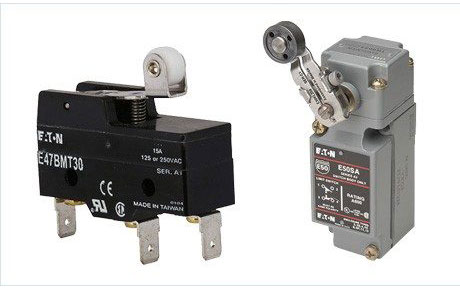
Limit switches and relays play a vital role in industrial automation, ensuring precise and reliable control of machinery. A limit switch detects the presence or position of an object using mechanical contact, while a relay serves as an electrically operated switch to control high-power circuits. Together, they form an efficient mechanism for automating tasks like stopping motors or activating alarms.
When paired correctly, these components can significantly enhance safety and functionality. Limit switches are typically used in conveyors, elevators, and industrial equipment where physical movement triggers a change in the electrical circuit. Relays act as the intermediary, converting small electrical signals from the limit switch into actions for larger electrical loads.

Wiring Configurations for Limit Switches and Relays
Proper wiring configurations ensure the smooth integration of a limit switch with a relay. Limit switches usually have Normally Open (NO) and Normally Closed (NC) terminals, while relays have coil terminals and contact terminals. Connecting these correctly is the first step to ensuring reliable operation.
Normally Open (NO): The circuit remains open until the limit switch is triggered, ideal for activating devices when movement is detected.
Normally Closed (NC): The circuit remains closed until the limit switch is triggered, useful for deactivating devices upon detection.
Relay Coil Terminals: Receive signals from the limit switch to control the relay.
Relay Contact Terminals: Control the external load, such as a motor or light.
For instance, in an industrial conveyor belt system, you may configure the limit switch to detect an object at the end of the line. The relay, in turn, activates a buzzer or stops the conveyor. Careful attention to wiring diagrams provided by manufacturers ensures that connections align with the intended operation.
Make sure you use the correct voltage rating for both the relay and the limit switch. Mismatched ratings can lead to system failure or electrical hazards.
Step-by-Step Guide to Connecting a Limit Switch to a Relay
Connecting a limit switch to a relay might seem complex at first, but breaking it down into simple steps makes it manageable. Follow this step-by-step guide to ensure a successful setup:
Gather Your Tools: Prepare the limit switch, relay, wiring diagram, multimeter, screwdrivers, and appropriate cables.
Identify Terminals: Locate the NO, NC, and Common terminals on the limit switch, as well as the coil and contact terminals on the relay.
Wire the Limit Switch: Connect one wire to the Common terminal and another to the NO or NC terminal, depending on your application.
Connect the Relay Coil: Attach the limit switch output wire to one of the relay’s coil terminals. Connect the other coil terminal to a power source.
Connect the Load: Wire the external device (e.g., motor or alarm) to the relay’s contact terminals.
Test the Circuit: Use a multimeter to ensure continuity and verify that the circuit behaves as intended when the limit switch is triggered.
This process ensures the relay operates correctly in response to the limit switch. Double-check your connections to avoid any shorts or operational failures.
Common Mistakes to Avoid During Wiring
Even seasoned professionals make mistakes when wiring a limit switch to a relay. Avoiding these errors can save time and prevent costly equipment damage:
Ignoring Voltage Ratings: Using mismatched voltage levels between the limit switch and relay is a common mistake. Always verify compatibility.
Improper Terminal Connections: Connecting wires to the wrong terminals can cause malfunctions or even damage the components. Carefully follow the wiring diagram.
Skipping Testing: Failing to test the circuit before powering it up can lead to undetected errors, potentially harming the system.
Loose Connections: Secure all wires properly to avoid intermittent connectivity issues during operation.
When in doubt, consult the manufacturer’s manual. A small oversight, like reversing the NO and NC terminals, can disrupt the entire operation. Take your time and verify each connection step-by-step.
Testing and Troubleshooting Relay Connections
After wiring, thorough testing ensures that the system operates as intended. Begin by inspecting all connections visually to confirm proper placement and secure attachments. Then proceed with these steps:
Perform a Continuity Test: Use a multimeter to check for continuity across the limit switch and relay terminals.
Simulate the Trigger: Manually activate the limit switch to observe if the relay responds correctly. This step verifies that the switch and relay interact as intended.
Check Load Operation: Ensure the external device connected to the relay (e.g., a light or motor) responds appropriately when the relay is triggered.
Address Faults: If the system doesn’t work, recheck connections for loose wires or misconfigured terminals. Replace faulty components if necessary.
Troubleshooting requires patience and methodical effort. Problems often stem from overlooked wiring issues or faulty components. Document the setup and changes during troubleshooting to streamline future maintenance.
Conclusion
Integrating a limit switch with a relay is a powerful way to automate industrial applications. By understanding the roles of these components, following proper wiring configurations, and avoiding common mistakes, you can ensure reliable performance. Testing and troubleshooting are critical to verifying the system’s functionality. With careful setup, this integration not only improves efficiency but also enhances safety in industrial environments.
