What Is A Debounce Circuit?
Key Takeaway
A debounce circuit is an electronic circuit used to clean up the signal from mechanical switches. When you press a button, the contacts can bounce, causing multiple unwanted signals. A debounce circuit removes this noise and provides a clean, stable output. This ensures that only a single transition is registered when the button is pressed or released. Debounce circuits are essential for accurate and reliable operation in digital systems, preventing false triggers and ensuring smooth signal transitions.
Definition and Importance of Debounce Circuits
A debounce circuit is a crucial component in digital systems designed to eliminate noise or “bounce” from mechanical switches or buttons. When a switch is pressed or released, the contacts can bounce multiple times before settling, causing multiple unwanted signals. A debounce circuit ensures that only a single, clean signal transition is registered. This improves the accuracy and reliability of digital systems by preventing false triggers and ensuring consistent operation. Debounce circuits are essential in various applications, from simple button presses to complex control systems, where precise and reliable input signals are critical for proper functionality. By filtering out these transient signals, debounce circuits enhance the overall performance and dependability of electronic devices.
Types of Debounce Circuits
There are several types of debounce circuits, each suited to different applications. Understanding these types is essential for selecting the right solution for your specific needs.
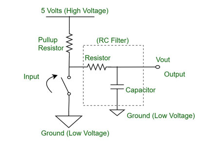
Hardware Debounce Circuits: These circuits use physical components like resistors, capacitors, and sometimes flip-flops or Schmitt triggers to filter out noise. A simple RC (resistor-capacitor) circuit can smooth out bouncing signals by delaying the signal changes until the bouncing stops. For instance, when a switch is pressed, the capacitor charges and prevents the immediate transmission of noise. This method is reliable and effective, especially for straightforward applications where a quick hardware fix is needed.
Software Debounce Solutions: In microcontroller-based systems, debounce can be handled by software. A common approach is to periodically sample the switch state and ignore changes that occur too rapidly to be genuine. This method is highly flexible and can be easily adjusted by modifying the software parameters. For example, you can program the microcontroller to read the switch state every 10 milliseconds and only register a change if it persists for a set period. This technique is ideal for systems where changes can be made quickly and inexpensively in software, without the need for additional hardware.
Hybrid Debounce Circuits: These combine both hardware and software approaches to ensure maximum reliability. The hardware component reduces the initial noise, while the software component refines the signal further. For example, an RC circuit might be used to handle the initial noise suppression, while a microcontroller handles the final filtering and decision-making process. This approach leverages the strengths of both methods, providing a robust solution for applications where reliability is critical, such as in industrial control systems.
By understanding these types of debounce circuits, engineers can choose the most appropriate method for their specific application. Whether you opt for a straightforward hardware solution, a flexible software approach, or a robust hybrid system, the goal is to ensure clean and reliable signal processing. Each method has its advantages and ideal use cases, so it’s important to consider the specific requirements and constraints of your project when making a decision.
You May Like to Read
Applications of Debounce Circuits in VFD Systems
In Variable Frequency Drive (VFD) systems, debounce circuits play a vital role in ensuring accurate control signals. VFDs control the speed and torque of AC motors by varying the frequency and voltage of the power supplied to the motor. Precise control inputs are essential for the smooth operation of these systems.
Control Panel Switches: Debounce circuits are crucial for accurately registering manual control inputs from switches and buttons on the VFD control panel. When an operator presses a button, the contacts might bounce, causing multiple signals to be sent instead of a single one. Debounce circuits filter out these false signals, ensuring that each press or release is accurately recorded. This precision prevents unintended commands, maintaining reliable operation and avoiding potential disruptions.
Sensor Inputs: In VFD systems where sensors provide input signals, debounce circuits are essential for filtering out noise and ensuring that only valid signals are processed. Sensors, especially those exposed to harsh industrial environments, can generate noisy signals due to interference or mechanical vibrations. Debounce circuits clean these signals, allowing the VFD to receive accurate data. This accuracy is critical for precise motor control, as erroneous sensor readings could lead to incorrect motor speeds or torque levels, affecting the overall performance.
Feedback Systems: Accurate feedback is crucial for VFD systems to maintain desired motor performance. Feedback mechanisms, such as encoders or tachometers, provide real-time data on motor speed and position. Debounce circuits ensure that these feedback signals are clean and free from noise, which is essential for the VFD to make precise adjustments. Clean feedback signals enable the VFD to maintain stable and accurate control of the motor, ensuring smooth operation and optimal performance.
For a new engineer, understanding the role of debounce circuits in VFD systems is essential. Proper implementation of these circuits ensures that control signals are accurate and reliable, which is crucial for the smooth operation of VFDs. By eliminating noise and false signals, debounce circuits help maintain the integrity of control inputs, sensor data, and feedback mechanisms, ensuring the VFD system operates efficiently and effectively.
In summary, debounce circuits in VFD systems enhance the reliability and precision of control inputs, sensor signals, and feedback mechanisms. They play a crucial role in filtering out noise and ensuring accurate signal processing, which is vital for maintaining the smooth and efficient operation of AC motors. For engineers, mastering the application of debounce circuits in VFD systems is key to designing robust and reliable motor control solutions.
Designing and Implementing Debounce Circuits
Designing a debounce circuit is a fundamental task for ensuring reliable digital signal processing, especially in systems involving mechanical switches and inputs. Here’s a guide to help you design and implement effective debounce circuits.
Determine the Bounce Duration: The first step is to measure the bounce duration of the switch or input device. This is crucial as it helps you determine the appropriate time constant for the RC circuit or the delay for the software debounce routine. You can use an oscilloscope to capture the bounce duration by observing the signal’s behavior when the switch is actuated. Understanding the exact duration of the bouncing helps in designing a debounce circuit that effectively filters out noise without delaying legitimate signals.
Select Components: For hardware debounce circuits, you need to choose resistors and capacitors with values that provide the required time delay. For example, an RC circuit designed to filter out a 5ms bounce might use a 10kΩ resistor and a 0.5µF capacitor. The choice of components should match the bounce characteristics of the switch. In software solutions, you implement a debounce algorithm that samples the input at intervals longer than the bounce duration. For instance, if the bounce duration is 5ms, the software might sample the switch state every 10ms to ensure only stable signals are registered.
Integrate with System: Proper integration of the debounce circuit with the system inputs is essential. For hardware debounce circuits, place the RC circuit close to the switch to minimize noise and ensure effective filtering. Ensure that the capacitor is connected across the switch and the resistor is in series with the input signal. For software solutions, the debounce routine should be called at the right point in the control loop, typically during the input processing stage. This ensures that only clean, debounced signals are used for further processing and decision-making.
Test and Adjust: After implementation, thoroughly test the debounce circuit under real operating conditions. Use an oscilloscope or logic analyzer to verify that the output signals are clean and free from noise. Adjust the component values or software parameters as necessary to achieve reliable operation. For example, if you notice that the circuit still allows some bounce through, you may need to increase the capacitance or adjust the software delay. Ensure that the debounce circuit consistently produces single, clean transitions for each switch actuation.
In conclusion, designing and implementing debounce circuits involves understanding the signal characteristics, selecting the appropriate method, integrating the circuit with the system, and thorough testing. By following these steps, engineers can ensure reliable operation of digital systems that rely on mechanical switches and inputs. Properly debounced signals prevent false triggers and enhance the accuracy and reliability of electronic devices. For new engineers, mastering these techniques is essential for creating robust and dependable systems.
Troubleshooting Debounce Circuit Issues
Troubleshooting debounce circuits involves a thorough examination of both hardware and software components to ensure proper functionality and reliable signal processing. Here’s a detailed guide to help you diagnose and resolve common issues in debounce circuits.
Verify Connections: The first step in troubleshooting is to ensure that all connections in the circuit are secure. Loose or corroded contacts can lead to intermittent signal issues, undermining the effectiveness of the debounce circuit. Check the solder joints, connectors, and wiring to confirm they are intact and free from oxidation or physical damage. A reliable connection is crucial for consistent signal integrity and effective noise filtering.
Component Values: Next, verify that the resistor and capacitor values in the hardware debounce circuit are appropriate for the bounce duration of the switch or input device. If the component values are incorrect, the circuit may not filter out the noise effectively. For example, if the capacitor value is too low, the circuit may respond too quickly, allowing bounce to pass through. Use a multimeter to measure the actual resistance and capacitance values and compare them with the designed specifications. Adjust the component values if necessary to match the expected debounce characteristics.
Signal Integrity: Use an oscilloscope to observe the input and output signals of the debounce circuit. This allows you to visually inspect the signal transitions and ensure that the output is clean and stable. Look for any signs of residual noise or bouncing in the output signal. A properly functioning debounce circuit should show a single, smooth transition corresponding to each switch actuation. If the output signal is not clean, re-evaluate the circuit design and component values to improve noise suppression.
Software Adjustments: For software debounce solutions, ensure that the sampling rate and delay parameters are correctly set. The sampling interval should be longer than the bounce duration of the switch. If the software samples the input too frequently, it may register multiple transitions for a single switch press. Review the debounce algorithm to confirm that it ignores rapid changes and only registers stable signals. Adjust the timing parameters as needed to achieve reliable debounce performance. For instance, if the bounce duration is measured at 5ms, set the sampling interval to at least 10ms to ensure accurate signal processing.
By following these troubleshooting steps, you can diagnose and resolve common issues in debounce circuits, ensuring reliable and accurate signal processing in your electronic systems. Properly functioning debounce circuits are essential for preventing false triggers and maintaining the integrity of control inputs and sensor signals. For new engineers, mastering these troubleshooting techniques is critical for ensuring the robustness and reliability of their designs. Through careful verification of connections, component values, signal integrity, and software parameters, you can optimize the performance of your debounce circuits and enhance the overall reliability of your electronic systems.
Conclusion
Debounce circuits are crucial for enhancing the reliability and accuracy of digital signals in electronic systems. By eliminating noise and ensuring clean transitions, these circuits prevent false triggers and improve overall system performance. For engineers, understanding and implementing effective debounce solutions—whether hardware, software, or hybrid—is essential for designing robust and reliable electronic systems. With precise control inputs and clean signals, systems like VFDs can operate smoothly and efficiently, maintaining high performance and reliability.