What Is A Logic Level?
Key Takeaway
A logic level refers to the state of a voltage in a digital circuit, which represents either a 0 or a 1. These levels are crucial for digital electronics, where they help determine how signals are processed. In positive logic, a low voltage (often near 0 volts) represents a logic 0, and a high voltage (like 5 volts) represents a logic 1. Conversely, in negative logic, these assignments are reversed: a high voltage represents a logic 0, and a low voltage signifies a logic 1. This concept is fundamental in understanding how electronic devices like computers and microcontrollers process and transmit data.
Definition and Importance of Logic Levels
A logic level refers to the specific voltage or signal state that represents a binary condition, typically 0 or 1, in digital circuits. These levels are crucial for the functioning of digital systems, as they define how devices interpret electrical signals to perform operations. Logic levels are fundamental in ensuring proper communication between different components of an electronic system. The correct interpretation of these levels ensures that digital circuits work reliably, as any misinterpretation can lead to malfunctions or data errors.
Types of Logic Levels
Understanding the different types of logic levels is crucial for designing and troubleshooting digital circuits, particularly in industries like VFD systems where precise control is essential. Here, we’ll discuss four common types of logic levels, each with distinct voltage standards.
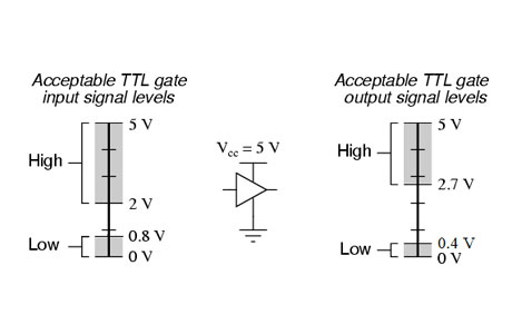
TTL (Transistor-Transistor Logic):
TTL logic levels typically operate at 5V. In TTL circuits, a voltage close to 5V represents a logic high (1), while a voltage near 0V represents a logic low (0). TTL is known for its robustness and noise immunity, making it a popular choice in early digital systems and some modern applications.
CMOS (Complementary Metal-Oxide-Semiconductor):
CMOS technology is versatile, operating at various voltages, commonly 3.3V or 5V. In CMOS circuits, a logic high is close to the supply voltage (e.g., 3.3V or 5V), and a logic low is near 0V. CMOS is preferred for its low power consumption and high noise immunity, which makes it ideal for battery-powered and high-density integrated circuits.
LVTTL (Low Voltage TTL):
LVTTL is a variant of TTL that operates at 3.3V. Here, a logic high is around 3.3V, and a logic low is near 0V. LVTTL provides a balance between the performance of traditional TTL and the power savings of lower voltage levels, making it suitable for modern digital devices that require efficient power use.
LVCMOS (Low Voltage CMOS):
Similar to LVTTL, LVCMOS operates at lower voltages, often 1.8V, 2.5V, or 3.3V, depending on the application. LVCMOS is used where power efficiency and high-speed performance are necessary. It provides logic levels appropriate to the lower supply voltages, maintaining the benefits of CMOS technology at reduced power levels.
Each of these logic levels serves specific purposes and applications, and understanding their characteristics is essential for designing reliable digital circuits. Engineers must consider the appropriate logic level based on the voltage requirements, power efficiency, and noise immunity needed for their particular application. This knowledge ensures compatibility and optimal performance across various components and systems.
You May Like to Read
Applications of Logic Levels in VFD Systems
In Variable Frequency Drive (VFD) systems, logic levels are integral to the control and communication processes, ensuring precise operation and coordination. These systems rely on logic signals to manage the speed and torque of electric motors by adjusting the frequency and voltage supplied. Here are the key applications of logic levels in VFD systems:
Control Signals:
Logic levels are used to start, stop, and adjust the speed of motors. These signals are essential for implementing commands that dictate motor behavior, ensuring smooth and efficient operation. For instance, a logic high might initiate a motor start sequence, while a logic low could signal it to stop.
Feedback Loops:
VFD systems employ feedback loops to monitor performance and make real-time adjustments. Sensors provide data on parameters such as speed, temperature, and load. Logic levels process this feedback, enabling the VFD to adjust its output to maintain optimal motor performance and prevent issues like overheating or overload.
Communication Interfaces:
Logic levels facilitate communication between the VFD and other control systems or networks. This interaction is crucial for integrating VFDs into larger automated systems, ensuring that they respond correctly to external commands and provide status updates. Accurate logic levels ensure that data is transmitted and received without errors, maintaining system reliability.
The precise interpretation and execution of commands through accurate logic levels are essential for the efficiency and reliability of VFD systems. Ensuring correct logic level usage in these applications helps maintain seamless operation, reduces downtime, and enhances overall system performance. This reliability is particularly important in industrial settings where any interruption can lead to significant productivity losses.
Interfacing Different Logic Levels
Interfacing components with different logic levels is a common challenge in electronics, but it is essential for ensuring seamless communication and operation in complex systems. Here are some key methods used to manage different logic levels:
Level Shifters:
Level shifters are dedicated devices designed to convert signals from one voltage level to another. These are crucial when interfacing components operating at different logic levels, such as 3.3V and 5V systems. By using level shifters, components can communicate effectively without risk of damaging the lower voltage components or misinterpreting signals.
Voltage Dividers:
Voltage dividers are simple resistor networks that reduce higher voltage levels to lower ones. This method is cost-effective and easy to implement, making it suitable for applications where precise voltage translation is not critical. For instance, a voltage divider can reduce a 5V signal to a 3.3V signal, making it compatible with lower voltage components.
Buffer Circuits:
Buffer circuits, or buffers, are used to isolate different parts of a circuit. They help in ensuring that signals are correctly interpreted without interference or loading issues. Buffers can also provide the necessary drive strength to pass signals between components with different logic levels. This isolation is particularly important in systems where signal integrity is critical.
Using these methods ensures that digital signals are accurately conveyed across components with differing logic levels, preventing errors and ensuring seamless operation. Proper interfacing not only enhances the reliability and functionality of the system but also protects components from potential damage due to voltage mismatches. For engineers, understanding and implementing these interfacing techniques is crucial for designing robust and efficient electronic systems.
Troubleshooting Logic Level Issues
Troubleshooting logic level issues involves a systematic approach to identify and rectify problems, ensuring the reliable operation of digital circuits. Here are the key steps:
Signal Measurement:
Start by using an oscilloscope or logic analyzer to measure the actual logic levels in your circuit. Compare these measurements against the expected values for each logic state. This helps in identifying discrepancies between the intended and actual signal levels.
Component Testing:
Check the individual components in the circuit to ensure they are functioning correctly within their specified voltage ranges. Use a multimeter to measure the voltage at different points and confirm that each component is receiving and outputting the correct logic levels.
Interfacing Check:
Verify that level shifters or other interfacing methods are correctly implemented and functioning properly. Ensure that these components are appropriately translating the logic levels between different parts of the circuit without introducing errors or signal degradation.
Power Supply Verification:
Confirm that all power supplies in the system are providing stable and correct voltages to all components. Fluctuations or incorrect voltages can lead to improper logic levels, causing erratic behavior in the circuit.
By systematically checking these areas, you can identify and resolve issues with logic levels, ensuring reliable digital circuit operation. This methodical approach not only helps in troubleshooting existing problems but also in preventing potential issues in future designs. Regular monitoring and maintenance of these aspects are crucial for maintaining the performance and reliability of electronic systems.
Conclusion
Ensuring compatibility with proper logic levels is essential for the reliable operation of digital systems, especially in complex applications like VFD systems. Understanding and managing logic levels helps in achieving accurate communication between components, maintaining system integrity, and optimizing performance. By using appropriate interfacing techniques and regularly troubleshooting potential issues, engineers can ensure that their systems function seamlessly and efficiently, regardless of the complexity of the application.