What Is A Voltage Divider?
Key Takeaway
A voltage divider is a simple electronic circuit that turns a large voltage into a smaller one. Using just two resistors connected in series, it divides the input voltage into smaller voltages. The key here is the ratio of the resistors: changing their values adjusts the output voltage, allowing precise control over how much voltage is outputted. This makes voltage dividers extremely useful for tasks like adjusting signal levels, setting the bias voltage in amplifiers, and measuring voltages safely. Common devices like the Wheatstone bridge and multimeters use voltage dividers to perform accurate measurements. Essentially, a voltage divider helps manage and manipulate voltages in many electronic applications.
Definition and Function of Voltage Dividers
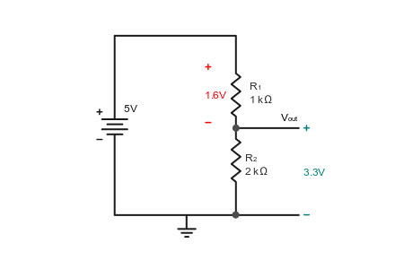
A voltage divider is a fundamental circuit used to reduce voltage to a desired level. It consists of two resistors connected in series across a voltage source. The input voltage is divided between the resistors proportionally to their resistance values, producing a specific output voltage.
Key Functions:
Adjusting Signal Levels: Reduces voltage to match different parts of a circuit.
Biasing Transistors: Sets the base voltage of transistors for proper operation.
Reference Voltage: Provides stable reference voltages in analog circuits.
Interfacing Components: Connects devices operating at different voltage levels safely.
Variable Voltages: Using a potentiometer allows for adjustable voltage outputs.
Impedance Matching: Ensures maximum power transfer and minimizes signal reflection.
Types of Voltage Dividers
Voltage dividers come in various forms, each suited for specific applications based on their components and configurations:
Resistive Voltage Divider:
This is the most common type, consisting of two resistors. The output voltage is determined by the ratio of the resistances. It is widely used for signal level adjustments and biasing in electronic circuits. The simplicity and effectiveness make it a go-to solution for many low-power applications.
Capacitive Voltage Divider:
Using capacitors instead of resistors, this type is primarily used in AC signal applications. Capacitors block DC but pass AC signals, making capacitive dividers ideal for frequency-dependent applications like signal processing and filtering.
Inductive Voltage Divider:
This type uses inductors to divide the voltage and is typically employed in radio frequency (RF) applications. Inductive dividers are less common but are valuable in circuits where inductance and frequency characteristics are critical, such as in RF amplifiers and antenna tuning circuits.
Adjustable Voltage Divider:
Incorporating variable resistors, or potentiometers, this type allows for dynamic adjustment of the output voltage. It is particularly useful in tuning circuits, calibrations, and situations where a precise and variable voltage is needed. Adjustable dividers provide flexibility in experimental setups and fine-tuning of electronic devices.
Each type of voltage divider has unique advantages tailored to specific needs, ensuring versatility in various electronic and electrical applications.
You May Like to Read
Applications of Voltage Dividers in VFD Systems
In Variable Frequency Drive (VFD) systems, voltage dividers are essential for precise control and signal processing. VFDs control the speed and torque of electric motors by varying the frequency and voltage supplied. Voltage dividers contribute significantly in the following ways:
Signal Scaling:
Voltage dividers adjust sensor signals to appropriate levels for the VFD controller. This ensures that the signals fall within the required range, enabling accurate monitoring and control of motor performance. Proper signal scaling is crucial for the effective operation of sensors and the overall VFD system.
Voltage Reference:
They provide stable reference voltages for the internal circuitry of the VFD. A consistent reference voltage is vital for maintaining the accuracy and stability of the VFD’s electronic components, ensuring reliable performance and minimizing errors.
Feedback Circuits:
In feedback circuits, voltage dividers help ensure accurate feedback from sensors, which is essential for maintaining precise motor control. Accurate feedback allows the VFD system to make real-time adjustments to motor operation, improving efficiency and performance while reducing energy consumption.
By effectively managing these critical functions, voltage dividers enhance the reliability and efficiency of VFD systems, making them indispensable in various industrial applications.
Advantages and Limitations of Voltage Dividers
Voltage dividers are simple and cost-effective components used in many electronic circuits, but they come with their own set of advantages and limitations.
Advantages:
Simplicity:
Voltage dividers are easy to design and implement, requiring minimal components, typically just two resistors. This simplicity makes them an attractive choice for many basic voltage adjustment needs.
Cost-Effective:
The components needed for voltage dividers, such as resistors, are readily available and inexpensive. This makes voltage dividers a cost-effective solution for voltage scaling and signal conditioning.
Versatile:
Voltage dividers are versatile and can be used in a wide range of applications to adjust voltage levels. They are suitable for interfacing different voltage domains, providing reference voltages, and scaling sensor outputs.
Limitations:
Power Dissipation:
Voltage dividers can waste power in the form of heat, especially when dealing with high current. The power dissipation is proportional to the current passing through the resistors, which can lead to inefficiencies.
Fixed Ratio:
Standard resistive voltage dividers provide a fixed voltage ratio determined by the resistor values. This lack of flexibility can be a limitation in applications requiring variable voltage levels or dynamic adjustment.
Loading Effect:
The output voltage of a voltage divider can be affected by the load connected to it. The presence of a load can alter the division ratio, reducing the accuracy and reliability of the voltage output. This loading effect must be carefully considered in circuit design to ensure proper operation.
By understanding these advantages and limitations, engineers can effectively utilize voltage dividers in their designs, optimizing their applications while mitigating potential drawbacks.
Designing and Implementing Voltage Dividers
Designing a voltage divider involves a few critical steps to ensure it meets the desired performance criteria:
Determine Voltage Levels:
Identify the input voltage (Vin) and the desired output voltage (Vout). This sets the foundation for selecting the appropriate resistor values.
Select Resistor Values:
Use the voltage divider formula: V out=V in× (R1+R2)R2
Here, R1 and R2 are the resistors used in the divider. By rearranging the formula, you can calculate the needed resistor values to achieve the desired Vout.
Power Ratings:
Ensure the resistors can handle the power dissipation. Use the power formula: P= RV 2
Calculate the power dissipation for each resistor and ensure their power ratings are sufficient to prevent overheating and damage.
Load Impact:
Consider the effect of the load connected to the voltage divider. The load resistance in parallel with R2 can affect the output voltage. To minimize this, use high-value resistors for R1 and R2 if the load has a significant impact.
Test and Validate:
Build the voltage divider circuit and measure the output voltage. Compare it with the expected value to confirm that it meets the design requirements. Adjust resistor values if necessary to fine-tune the output.
By following these steps, you can design and implement an effective voltage divider that meets your voltage scaling needs while considering power dissipation and load impacts. This process ensures reliability and accuracy in your electronic circuits.
Conclusion
Voltage dividers are fundamental in electrical and electronic circuits, enabling precise voltage adjustments necessary for various applications. They are vital in VFD systems for signal scaling, providing reference voltages, and ensuring accurate feedback. Despite their simplicity, careful design and consideration of limitations are essential to maximize their effectiveness. Properly implemented voltage dividers enhance the performance and reliability of electronic systems, making them indispensable tools for engineers and technicians.